Edge detection using the Sobel operator
In image processing, a lot of useful information in an image is contained in the edges of objects, and edge detection is a process of separating the object edges and the rest of the image (objects themselves and their environments). Obtained information can then be used for further analysis, such as detection of faces, boundaries, or other image processing procedures such as superresolution (e.g. deciding whether to continue a gradient or place a sharper border between new pixels could depend on whether an edge is being processed).

- edge detection applied on a CGI image
The goal of an edge detection algorithm is to identify the pixels that are more likely to belong to an edge. This can be accomplished by setting the pixels which the algorithm deems belong to an edge to 0, and those that do not, to 255, on a grayscale image (or just converting it to a black and white bit string). The end result of the mentioned filtering process can be seen in the first image.
In the Sobel procedure, determining how likely a pixel belongs to an edge is based on the fact that the rate of change in brightness along edges of objects tends to be higher. The gradient for brightness is taken for every pixel in the image, in the form of a 2-dimensional vector (change in X axis, and Y axis), and the magnitude of that gradient vector corresponds with the likeliness of the pixel being a part of an edge.
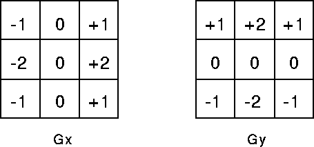
The Sobel operator is used for calculating the gradient vector (the rate of change for a point, with a direction) for each pixel. Concretely, it involves iterating over every pixel in the image, and using the following two matrices to calculate the X and Y components of the gradient vector:

- matrices for calculating the gradient components
The center cell represents the current pixel, and other cells represent neighboring ones. The outermost layer of pixels (from [0, 0] to [width-1, 0] and [0, height-1], etc) is problematic, since they do not have a full neighborhood. In my implementation they are ignored, since a single layer of pixels should not carry that much information and can thus be discarded.
For each position in the image, the values of the pixels covered by a matrix (pixel at current position + neighboring pixels) are multiplied by the coefficients in each cell of the matrix (each pixel by its respective cell), and added to a sum. Depending on the matrix, these sums represent the X and Y components of the gradient vector.
Above matrices work on a rather simple principle. First, the center cell has a coefficient of 0 that represents the pixel being processed. Since the algorithm is interested in finding the rate of change of that pixel in respect to its neighborhood, the pixel’s own value can be ignored, because it has no direction information (it will be used in the next step for calculating the gradient of the right pixel, though). The two center-horizontal outer cells have values of -2 and +2 respectively, because their pixels are the closest to the current one on the X axis. The sign signifies direction.
For example, if there was a row of pixels under the matrix with values of [255, 255, 255] (top and bottom rows ignored for simplicity), the X component of the gradient vector would be 0. And that makes sense because the rate of change for the center pixel really is 0 – its two neighbors have the same value (this can be visualized by two physical forces of the same quantity dragging an object in two opposite directions – the object doesn’t change its velocity). If it was [255, 0, 255], it would still be zero, because the rate of change in both directions on the X axis is the same – but for both the left and the right pixels, it could hold a non-zero value.
The same method is used for calculating the Y component, and afterwards, the magnitude of the gradient vector can either be approximated by adding up the absolute values of the components, or calculated with the proper formula (Pythagoras’ theorem), to get the final value of the edge quality for that pixel. A low magnitude means the pixel is less likely to be a part of an edge. To get the final result (first image in post), where the edges are concretely identified or visualized, one only needs to set a threshold for the magnitudes of the gradients, over which the pixels are declared a part of an edge, and under which, the pixels are declared part of either the background, or the object itself.
You can find the Processing source code on my GitHub: github.com/corazza/edge-detection.